Practical propagation environments
Complicating factors in practice
So far we have only studied a few idealized propagation environments. These simple environements helped us to understand the key concepts (e.g., coherence distance, coherence time, coherence bandwidth, etc.), which apply to more complicated propagation environements. Now we would like to discuss some examples of complicating factors in practice.
Reflection from a gound plane
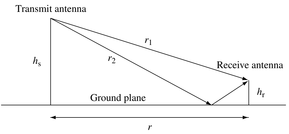
In practice, the transmit antenna and the receive antenna are rarely at the same height. The base stations are usually on the top of buildings, and the mobile devices are mostly on the ground. Therefore, there is a path where the signal is reflected on the ground. This path has a similar distance to the line-of-sight (LOS) path, especially when the distance between the transmitter and the receiver is large. Due to the phase shift, the signal from the reflection path is destructive to the signal from the LOS path. As a result, the power of the signal decays in the order of \(r^{-4}\), much larger than \(r^{-2}\) in the previous examples.
Obstables and shadowing
In practice, there may be also obstacles that block the LOS path between the transmitter and the receiver. Since the LOS path has the shortest distance, the signal from the LOS path is usually the strongest. When the LOS path is blocked, the signal strengh might decrease dramatically. This is particularly common when the mobile device is indoor, where the building walls and objects inside the room can be obstacles. This is why the signal may be weaker in buildings.
The degradation in channel quality due to blockage is called shadowing. The challenge of shadowing is that it lasts longer, compared to the destructive interference in multipath fading. Recall that in multipath fading, the signal strength changes in the order of the wavelength (the coherence distance is \(\frac{1}{4}\) of the wavelength). So the signal may be in deep fading only for a short time if the fading results from multipath. In contrast, shadowing can last for seconds.
Realistic reflectors
In our previous examples, we assumed that the wall is a perfect reflector that does not absorb the energy of the signal and create a phase shift of exactly \(180^\circ\). In practice, the reflectors may absorb energy and induce different phase shifts. This will alter the power decay.
There are also other types of reflections such as scattering (e.g., on a rough surface) and diffusion, which require different models.
Ray tracing versus statistical models
Although there are many complicating factors in practice, these factors ultimately change the magnitude and the phase of the signal. Therefore, if we have a precise map of the propagation environment (e.g., locations of buildings, materials of the building walls, windows), we can use the ray tracing method to get a relatively accurate “map” of channel quality.
While the ray tracing method is accurate, they have limitations. First, it may be computationally intensive to calculate, especially when the environment is changing so that we need to update the channel quality map regularly. Second, we would need different maps for different environments.
On the other hand, we can also develop statistical models that are not as accurate but are approximately valid for a large number of environments. For example, there are standard path loss models for the metropolitan environment, the rural environment, and so on.
There are trade-offs between the ray tracing model and the statistical model. We will choose the appropriate one based on our purpose. For example, in academic research, people tend to use the statistical model for its generality and its simplicity in analysis. In standardization, people need to use more accurate models to evaluate the performance of different algorithms in practice.