Case 1: Fixed antennas in the free space
The simplest environment
We start with the simpliest propagation model. Consider a transmitter anteanna, radiating into free space, and a receiver antenna in the far field (i.e., far away from the transmitter). There is nothing else in the space, so that the only propagation path for the signal is the line-of-sight (LOS) path from the transmitter to the receiver.
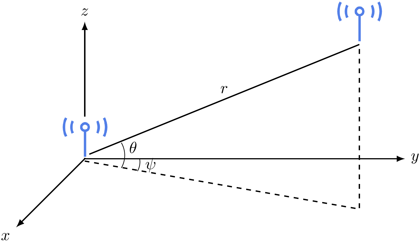
We can create an 3-dimensional coordination system with the transmitter antenna at the origin. Then the location of the receiver antenna can be described by a triple \(\mathbf{u} = (r, \theta, \psi)\), where \(r\) is the distance between the antennas, \(\theta\) is the vertical angle, and \(\psi\) is the horizontal angle.
To make things simple, we let the transmitter send a sinusoid at frequency \(f\): \[ \cos 2 \pi f t. \] This is without loss of generality, because most signals are the superposition of sinusoids.
In this simplest possible environment, we can analytically determine the received signal as \[ E_r(f,t,\mathbf{u}) = \frac{\alpha(\theta,\psi,f) \cos 2 \pi f (t - r/c)}{r}, \] where \(c = 3 \times 10^8\)m/s is the speed of light.
Breakdown
Now let us break down the above equation.
- First, the received signal is still a sinusoid with the same frequency \(f\). But the phase is delayed by \(2 \pi f r / c\), which happened because the signal traveled across a distance of \(r\) at the speed \(c\).
- Second, the magnitude of the received signal depends on the function \(\alpha(\theta,\psi,f)\), which represents the antenna gain. The technical term is radiation pattern of the antenna. The figure below shows an example of the radiation pattern in the horizontal plane:

By Timothy Truckle; Link: https://commons.wikimedia.org/w/index.php?curid=4245213 - We can see that the antenna magnifies the signal to different levels at different angles. The figure above shows the radiation pattern with respect to the horizontal angle \(\psi\). As you can imagine, there is another radiation pattern with respect to the vertical angle \(\theta\).
- Since both the transmitter antenna and the receiver antenna have radiation patterns, the function \(\alpha(\theta,\psi,f) = \alpha_s(\theta,\psi,f) \cdot \alpha_r(\theta,\psi,f)\) is the product of the transmitter antenna radiation pattern \(\alpha_s(\theta,\psi,f)\) and the receiver antenna radiation pattern \(\alpha_r(\theta,\psi,f)\).
- Third, the magnitude of the received signal is inverse propotional to the distance \(r\). This indicates that the power of the signal decreases as \(r^{-2}\). This is the large-scale fading. Note that the exponent of \(-2\) may change with the actual environment (i.e., raining or existence of other objects in the environment).
Take-away
In summary, in a free space, the received signal attenuates by \(r^{-2}\). The frequency \(f\) does not change. The phase is delayed due to the distance. Nothing particularly interesting here.
We will see something more interesting in more complicated environments.